The input data for a plate cam with a translating roller follower is explained below:
Watch this video to see how to enter the Kinematic data and then watch this video for the Geometry.
|
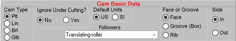
Basic Data |
|
|
In this section there will be a list of cams and followers that are available with the version of the program for the license purchased. The other controls here are the Ignore Under Cutting that is set to no by default. This is a choice that should be taken with care. Default Units will change all the units in the edit boxes to US Customary, or SI. If numbers are in the edit boxes, they will be converted to the choice made. Face or Groove allows for computing the cam surface(s) desired. For a face cam, the surface can be Inside (In, or push cam), Outside (Out, pull cam). The dropdown allow for the choice of follower. |
|
|
|
|
|
Cam Picture |
|
|
Shows the explanation of the data required. Click the right mouse button over the cam picture for a zoomed view. |
|
|
|
|
|
Crowned Follower & Radius |
|
|
A follower may be a cylinder with straight sides, or may have a radius on the side. Normally, the radius of the crown is 30 inches, or 762 mm. The crown will allow contact in one location and therefore, will increase the contact stress. Cam Designer SE will compute the contact stress according to the radius of the crown; for straight sides the radius is "infinite", so the contact stress is considerably lower. |
|
|
|
|
|
Groove Width/Rib Thickness |
|
|
If the cam is a groove (box), or rib, enter the appropriate dimension here. The default for a groove is the follower diameter + clearance. The clearance is set in the Preferences/Geometry. |
|
|
|
|
|
Contact Width |
|
|
Contact width is necessary for computing the contact stress for a non-crowned follower. |
|
|
|
|
|
Stem Angle |
|
|
The default for stem angle is 90 deg. For computing the loads on the cam and the torque to turn the cam, the accurate entry here is important. Gravity is assumed to be at 270 degrees, or in the negative Y direction. |
|
|
|
|
|
Follower Offset |
|
|
A follower may have an offset from a line directly through the center of the cam. The follower axis, then, will be translating parallel to this line. Adding offset either positive, or negative can help the pressure angle if applied correctly. |
|
|
|
|
|
Follower Loads |
|
|
Follower loads may be applied here. Spring Rate (Spring Constant) is for a linear spring. Spring Preload is the amount of spring load at it's undeflected position. Damper Constant is for a shock absorber. Follower Mass is the weight of the entire follower system. If the stem angle is 90 degrees, all of this mass will be on the cam at all times. Cam Designer SE will apply this load according to the stem angle. Follower Preload is a load that would be applied in addition to the Follower Mass, normally, this will be zero. Varying Loads are loads ( force/torque, or mass/inertia) that are applied at certain places in the cam cycle. See Varying Load Dialog and the video for this. |
|
|
|
|